
I got around to quite a few (for me!) projects this year and they practically all had one thing in common: they cost nothing for materials. Also, as is usual for me, the designs changed often. If you’ve ever made anything from scratch, to your own plan, I think you’ll find some of these themes familiar.
Vertical Monitor stand
There are a bunch of technical reasons to turn a monitor on its edge, and another bunch of technical problems to solve when you do so. But this post isn’t about that, although I did write a post on the techie bits which you could look at here: Multiple Monitors. Let’s keep it simple and say I always wanted one, and there wasn’t room on my desk unless I turned one monitor on end.
When I built a drawer unit in my workshop, the lumber store messed up the cutting and had to do it over. They didn’t want the bits from the first attempt, so I still have some MDF pieces left from that. And there was also a piece of oak ply left from the time I made the desk in my office, which I thought would match the desk, because, well, it was made from the same stuff.
The first design wasn’t bad. I knew I had to make the base wide enough so the monitor wouldn’t topple, and I made a piece with two angled arms which gave stability in the forwards direction and provided a neat place to corral stuff in front of the stand.

I even had a way to adjust the tilt – if you really cranked down on the knob, that is. The main flaw was that I had designed it so that the bottom edge lined up with the bottom edge of the main monitor, and I found that that made the top edge too high up to read easily with bifocals – neck strain alert!
To lower the screen, the arms were in the way, and they weren’t doing a great job of anti-topple, so they had to go. The simple solution was to chop off the two arms, drill a new mounting hole lower down, and slap the whole thing on a wider base. So the wonderful bit of oak plywood is never seen. The new pivot point precludes any kind of serious tilting, so that’s gone the way of the dodo as well. Maybe I should reclaim the nice knob and just use a threaded nut – especially now that I know what each knob costs if you buy just one.
All said and done, this was a success. It does exactly what I want and it hasn’t fallen over. And all the errors, er, design changes, are around the back where I don’t see them.

Carpet knife rebuild
I’m not sure where I inherited them, possibly from the owner of our first house, who left a pile of tools when he moved to a condo, but I have two wooden-handled carpet knives. They have non-disposable curved blades which you have to actually sharpen, not replace, when they get dull. And they are great for digging grass and weeds out from the cracks between paving stones. I don’t do carpet. I’m not sure why I do weeds.
Anyway one day last year I was using the smaller knife when I went to stand up, and without thinking, I used the knife to steady myself. Apparently the blade wasn’t designed for that, and it snapped off.

(I’m not quite sure what I was thinking when I chose shiny plastic as the backdrop for this photo, but I’m not taking the thing apart again for a re-take.) Anyway, my challenge was to find a piece of metal that I could cut into the same shape as the old blade.
What I came up with was a strip of metal which was once one of the supports under the mattress of Adam’s crib. This had withstood the trauma of Adam using the crib as a trampoline, so it was pretty tough stuff. The only issue was that it was not very wide, so even placing the old blade on it at an angle, I couldn’t get the full “hook” at the end of the blade. So I compromised a bit.
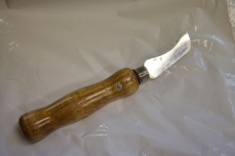
I guess polishing the blade was a bit over the top considering I was going to be digging it into sand between rough pavers, and if I was going to go that route, I should have started with a clearer section of metal, but it is what it is, and it’s doing a great job.
Mobile tool cart
This was one of those projects that started for all the wrong reasons. And although I did make a plan, I never really did a needs analysis. Anyway, once upon a time there was an office chair, which, as anyone knows, is designed so that the air lift will fail within two years, and the specs for said air lift never match any replacement part you can find. For some reason, the base for this chair (minus the actual chair bit) sat around my workshop for a year or five, awaiting a purpose. You know, one of these:

It still had the castors back then. I was struck by how mobile this base was, and how stable it was, given it had five points of contact. I began to visualize some kind of wooden saddle attached to the top plate, hanging down on either side, and a tower of drawers or cubby holes rising above it, ending with a flat top at the same height as my table saw, so it could assist when I needed to support a large sheet of material. The storage would be filled with the tools I used most, the wheels would let me move it to where I was working. I even thought it would have some kind of camera support built in, so I could wheel it to whatever I wanted to record and not have to worry about vibrations spoiling the video.
Unfortunately, what looked reasonable on paper began to look untenable in the harsh light of the workshop. To begin with, the idea of bits hanging on either side of the central arm left a lot of empty space going unused in the centre. I took the castors off and put them on a rectangular base, reclaiming the centre. While I suppose I could, at this point, have made the base larger, I still wanted it to be agile, not lumbering (little woodworking pun there). That meant that if the height matched the table saw, I felt it would be prone to tipping, so I kept it relatively short. (Besides, my available sheet goods weren’t that long!)
The telescoping post for the camera support just wasn’t going to work either. Now that the unit was shorter, the total height for a post would not be adequate. My solution to this problem was quite inspired, if I say so myself, and begat the “Camera Stand” project that I’ll describe later.
Those were the main design changes. The rest were structural changes, which I won’t bore you with too much, but let’s just say that 3/4″ material is easier to connect to and from. My top and bottom happened to come from the 1/2″ MDF pile, and so my plans for using pocket hole screws up into the 1/2′ material weren’t too practical.
Here’s how it looks:
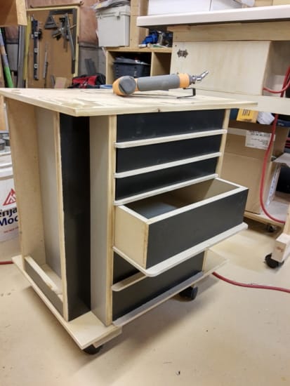
I have to say I expected it to be a bit taller! The drawers can be pulled out from either side, so that improves accessibility if the cart is wheeled into a confined area, and it also means I can use the full interior of the drawers without needing full extension drawer slides. However, that means the whole design would be prone to racking, but that is addressed by the buttresses at each end, which also provide closed in areas where I can hang tools like hammers. There are solid wood pieces on the bottom which provide a bit of extra height, a place for pocket screws to attach to and enough depth for the castor pivots to sink into.
Adam and Anna both contributed to the materials. Apart from the MDF top and bottom, the sheet goods came from a desk that Anna demolished, and the drawer bottoms are left over from some sheet goods that Adam used to cover the walls in an alcove we added in his home. The edges are all trimmed with cedar left from making garden frames, and the finish is polyurethane from touching up the floor in Adam’s old room.
I still need to decide whether to make individual hangers for each tool, or if I should put pegboard on each end and use commercial hangers that I have never put back up since moving to this workshop. Probably a combination.
Camera arm
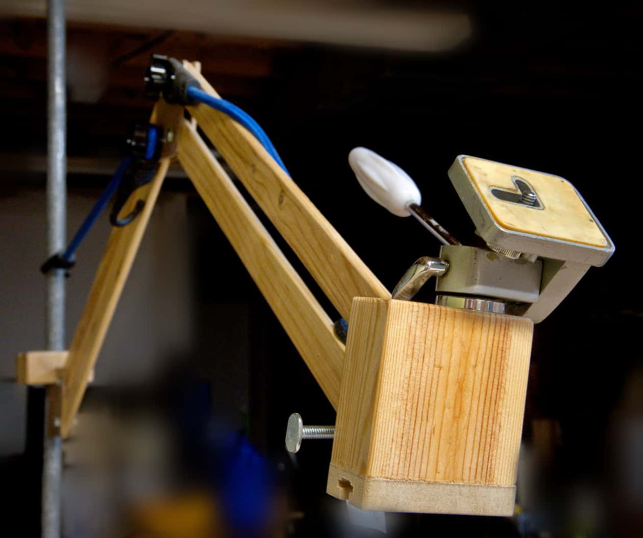
The camera arm I want has two aspects. Firstly, the vertical component I alluded to in the tool cart description; something that allows for gross adjustments in the camera’s height. The other part moves away from the support and provides a way to attach the camera at the end, while allowing fine adjustment of the camera angle.
I was thinking of drilling a hole in the top of the tool cart, near the front corner in the photo above. Then some kind of pipe would fit in the hole, and the height could be adjusted somewhat by pulling the pipe up and fixing a height by tightening a collar. When I was looking around for suitable pipe, I came across my pipe clamps. My first thought was that I could use the cart for storing one or two clamps, which could support a camera when they weren’t clamping.
Then I mentally turned the clamp end to end, and realized that I could clamp the thing to anything with an overhang. I could even drop one from the workshop ceiling. Or clamp it to one corner of the cart.
Well, on to the horizontal component. I have to admit that this is still a work in progress.
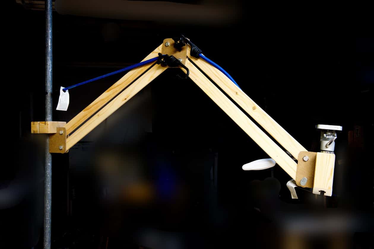
I based my design on a parallelogram arm used in an office light I’ve had for years. The advantage of this is that the camera support stays at the same angle as its moved away from the vertical post. So if, for example the camera is pointed straight down, it will be that way whether it’s close to the post or fully extended away from it.
The problem, of course is the leverage applied to all the parts which increases as the arm extends. You can’t tighten the screws at the centre elbow enough to keep the arm extended! My light has springs to help offset the weight – that’s what the bungee cords are simulating. I have sourced some springs (my first project-related purchase this year!) but not tested them yet.
I was trying to keep everything light, and the wooden slats are strong in one dimension, but easily wander (and twist) in the other, as you can see in the second picture. The connection at the post end also needs re-design; I wasn’t looking at the forces when I made it, and while it works, I’m not sure how it will stand up. Finally, the camera end is still a work in progress. Frankly, I haven’t dared hang a camera on this thing in it’s current state.
This has been the first time I’ve tried to “engineer” a solution, rather than just overbuilding it (if a 2×4 doesn’t work, try a 2×6). It’s frustrating and fascinating. I wish I had more experience working with metal. I’m thinking of playing with some aluminium rods that comprised the railings on our neighbour’s old deck. Stay tuned!
DVD storage
This project started when the wooden floors in the house were refinished – back in 2015. I had to move everything out of my study, including over 500 DVDs. Ever since then they have been stored in bundles of about twenty DVDs. Not the best for finding a specific movie! Now, a DVD is 5″ deep by 8″ high, more or less. Bookshelves tend to be twice as deep even adjustable height book cases are mostly more than 8″. So… custom build!
Looking around, I noticed a 4×6 foot table top thing that was intended as a base for a model railway. It moved to this house in 2003 and had never been touched, let alone used, so it was fair game. A model railway doesn’t need a real smooth surface, because it should be totally covered in fake grass, mountains and rivers. So we got the cheapest 1/2″ plywood we could find, put 2×1 spruce around the edges and a bit of framing on the underside and called it done. Cheap underlay plywood is not what you would call “smooth”, by the way, and that meant that half the time I considered this build a prototype, and the other half I was trying to put lipstick (well, red paint) on a pig.
So, the plan was simple, the shelves would be 4′ long, or as close as I could get after cleaning up the edges. 8″ spacing meant 5 shelves with a bit left over from 4′ sides, So I cut 8 pieces 5″ wide and almost 4′ long, cut some dadoes in the sides and glued it together. Well, of course it didn’t really go down that way, but it did get done. Theoretically it will handle about 450 DVD cases.
Most of my time was spent trying to deal with the fact that 1/2″ is not that thick. So dados in the sides couldn’t be very deep, and even if DVD cases aren’t that heavy, 90 of them adds up, the shelves are almost four feet long and did I mention that 1/2″ plywood is not that thick?
When I wasn’t worrying about the span, I was worrying about the thing standing up. It is four foot high and five inches wide. That’s not a big footprint. So I began to design for the thing to hang on a wall, but the load bearing pieces are the two sides, and there would not be studs directly behind the sides, so how would I transfer the load to the studs?
I think I had solutions to these problems, but when I carried the thing from the workshop to the exercise area the first impression was how heavy the thing was (before loading it with 450 DVD cases). When I set it down in front of the studs where I was going to attach it, I realized two things: that location wasn’t as convenient as I had imagined, and the top cleat that I was going to hang it from was an ideal way to attach the unit to the studs – with the two sides firmly set on the concrete floor.
So, until I load it up and find it fails catastrophically, this is the final design and placement. The back is made from pegboard because I had pegboard which was going to be a sliding panel/wall between the workshop and the furnace area in our last house. I also thought that none of it would be visible behind 450 DVDs, except for the bit at the top, but that I had planned to be out of sight, above eye level. New plan – put some DVDs on the top shelf as well. Bonus, that increases capacity to 540.
Incidentally, my strategy for avoiding shelf droop was to glue and staple each shelf to the pegboard back and to make exact height separators which would support each shelf in the centre, transferring load to two stringers under the bottom shelf.
Besides, I’m sure the red paint will help make it stronger. Anna put the second coat of paint on, by the way. Thanks, Anna.

Bonus Quickies
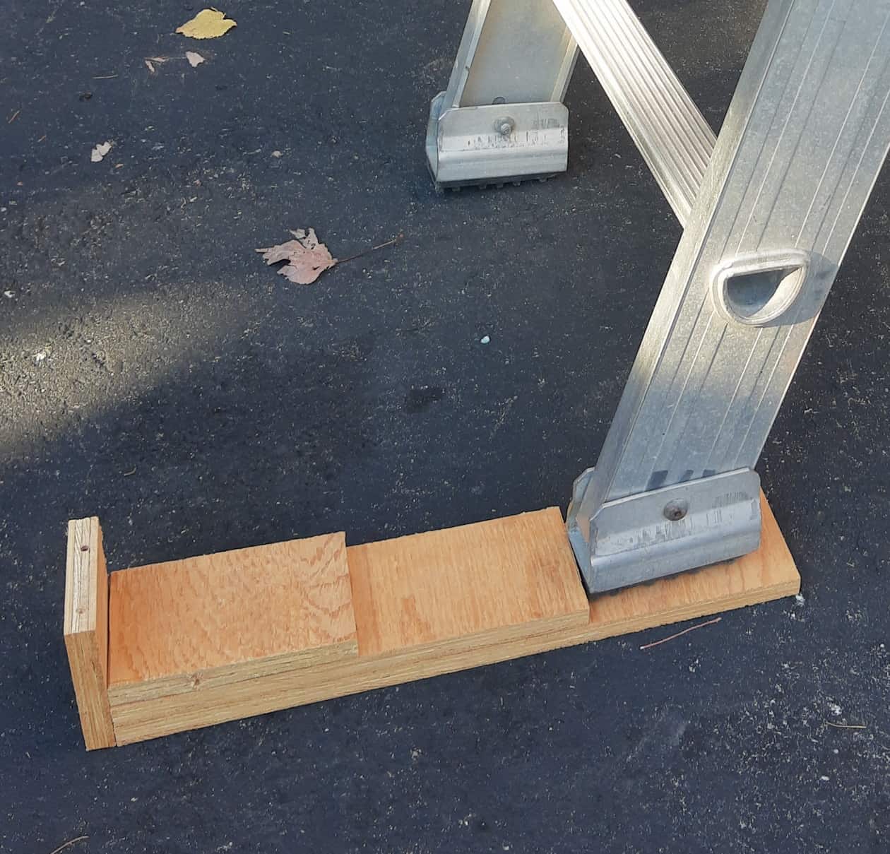
When I put up the Christmas lights, there is always a point where the surface under the ladder is not perpendicular to the ladder. Normally, I deal with this by digging in the recycle bin for either cardboard or newspaper, and folding it enough times to bring one side up to the level of the other. This year I spent a whole ten minutes and threw together a ladder step thingy. Catchy name, eh? As it’s made of 1/2″ plywood (guess where that came from!) it will raise one leg of the ladder by 0.5, 1.0 or 1.5 inches.
The other fix is one I have been doing for countless years. I forget when I made the first version, but the one I just took off was made in 2008. I’m talking about the strip of oak that I screw to the bottom of the clunkiest, heaviest snow pusher you have ever seen. When the plastic (or maybe it was metal, who remembers?) snow pusher bit the dust , the handle was still in good shape, so I joined two boards at an angle and bolted on the old handle. It turned out to be my favourite pusher for quickly clearing light snow. It’s wide, so it takes less trips to and fro, and it’s heavy enough to stay down on the surface, and has decent momentum to shift the occasional bit of ice.
In a stroke of genius, I chose to attach a wear strip where it scrubs along the driveway. This strip wears down over time, and I take it off and attach a new one. I usually make up several at a time, and this year I needed a new batch. Luckily I found someone throwing out a dumpster load of oak flooring boards a year or three ago, and after removing a wicked looking staple and trueing up an edge, I got three free replacements. Given that they seem to last three or four seasons, I have to wonder if I’ll still be pushing snow in my mid eighties. Well, why not?


2 responses to “Free Workshop Projects”
At first I was going to mention that while I was reading your items. You hadn’t posted any photos. But then I went to the next page and they suddenly appeared. Course it is 2:21 a.m. and my eye sight is probably not the best. Always enjoy reading your notes David. You make it sound like a lot of fun while you are putting together all your tasks. MaryJoe must be so pleased with all of your crafting etc.
Wishing you and your family a very Merry Christmas and a Happy New Year to all of the Powell family. I am sure Mary Jo will be baking up a storm too.